





A single 156mm x 156mm monocrystalline wafer can carry a microcrack as thin as 5 microns, invisible to the naked eye but capable of propagating into a fracture that reduces cell output by 10 percent or more within a year of field deployment. Photovoltaic manufacturers running lines at 3,000 to 6,000 wafers per hour cannot rely on manual sampling to catch defects at this scale, which is why machine vision systems have become the default inspection layer across cell fabrication, module lamination, and final panel testing. These systems combine high-resolution sensors, precision optics, and pattern-recognition software to flag flaws in milliseconds, at throughput rates no human inspector could sustain across a full shift.
The economics are straightforward: a single undetected microcrack that reaches a customer installation can trigger a warranty claim worth far more than the incremental cost of an inline inspection station. As wafer thicknesses continue to shrink toward 130 microns to reduce silicon consumption, the mechanical fragility of the material increases, and the tolerance for missed defects shrinks correspondingly. This article examines the technical building blocks of machine vision inspection for solar manufacturing, from lens selection and lighting geometry to the role of machine learning vision systems in classifying ambiguous defects that rule-based algorithms struggle to categorize. machine vision lenses

What Defects Do Machine Vision Systems Need to Detect in Solar Manufacturing?
Solar production introduces a defect taxonomy that differs from most other electronics manufacturing. Microcracks, finger interruptions in the screen-printed silver grid, chips along wafer edges, saw marks from ingot slicing, and electroluminescence anomalies invisible under normal light all require different imaging approaches. Contamination from handling, such as fingerprints or particulate residue, can also degrade cell efficiency without producing a visible structural flaw, which means inspection systems must combine surface-texture analysis with electrical or photoluminescence imaging in some configurations.
Color and reflectivity variation across anti-reflective coatings adds another layer of complexity. A coating applied unevenly by even a few nanometers can shift the apparent color of a cell under standard illumination, and while this rarely affects performance directly, it does indicate a process drift worth flagging. High-quality machine vision systems designed for this sector typically integrate at least two imaging modalities, visible-light and near-infrared or electroluminescence, to separate cosmetic variation from functional defects.
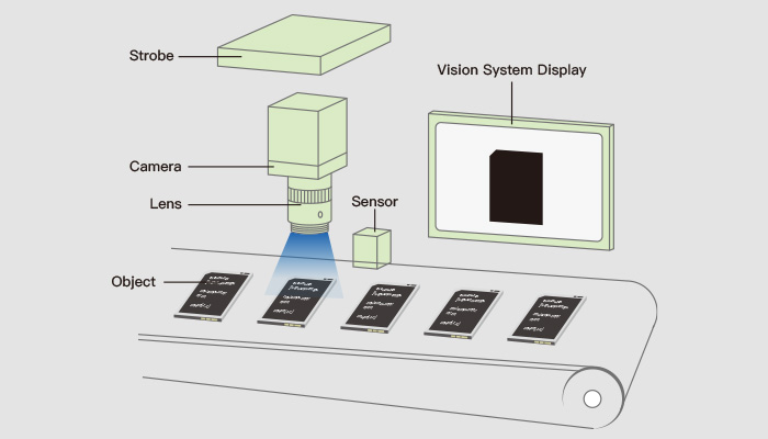
How Do Camera Resolution and Lens Selection Affect Defect Detection Rates?
Resolution requirements in wafer inspection are dictated by the smallest defect that must be reliably resolved, not by an arbitrary preference for higher megapixel counts. A common rule of thumb is that a defect should span at least 3 to 5 pixels across its narrowest dimension to be reliably classified by software rather than merely detected as noise. For a 156mm wafer where the target minimum crack width is 20 microns, this implies a field of view requiring sensor resolution in the range of 12 to 25 megapixels, depending on whether the entire wafer is imaged in one frame or scanned in strips.
Machine vision lenses for industry applications must match this resolution with sufficient modulation transfer function performance at the sensor’s pixel pitch, otherwise the extra resolution is wasted on a soft image. Telecentric lenses are frequently specified for wafer edge inspection because they eliminate perspective distortion, which is critical when measuring chip depth or edge chamfer angles to sub-10-micron tolerances. For full-wafer surface scanning, a fixed-focal-length lens with low distortion and consistent illumination across the field is usually preferred over telecentric optics, since the larger working distance and field of view make true telecentricity impractical. industrial lenses
Line-Scan Versus Area-Scan Cameras: Which Fits Wafer Inspection Lines?
Line-scan cameras dominate high-speed wafer and panel inspection because production lines move material continuously rather than stopping for discrete image capture. A line-scan sensor with 4K to 16K pixels captures a single row of the wafer surface as it passes beneath the camera, and the system software stitches successive rows into a complete image synchronized to encoder pulses from the conveyor. This approach avoids motion blur entirely, since exposure time per line can be reduced to microseconds, and it scales naturally to wafers or panels of varying length without changing the optical setup.
Area-scan cameras remain the better choice for stop-and-inspect stations, such as post-lamination panel checks where the unit is briefly stationary for junction box or frame verification. They also suit applications where multiple features across the full 2D field must be correlated simultaneously, such as verifying busbar alignment relative to cell edges. Choosing between the two is less about image quality and more about matching the camera’s acquisition model to the mechanical handling system already installed on the line.
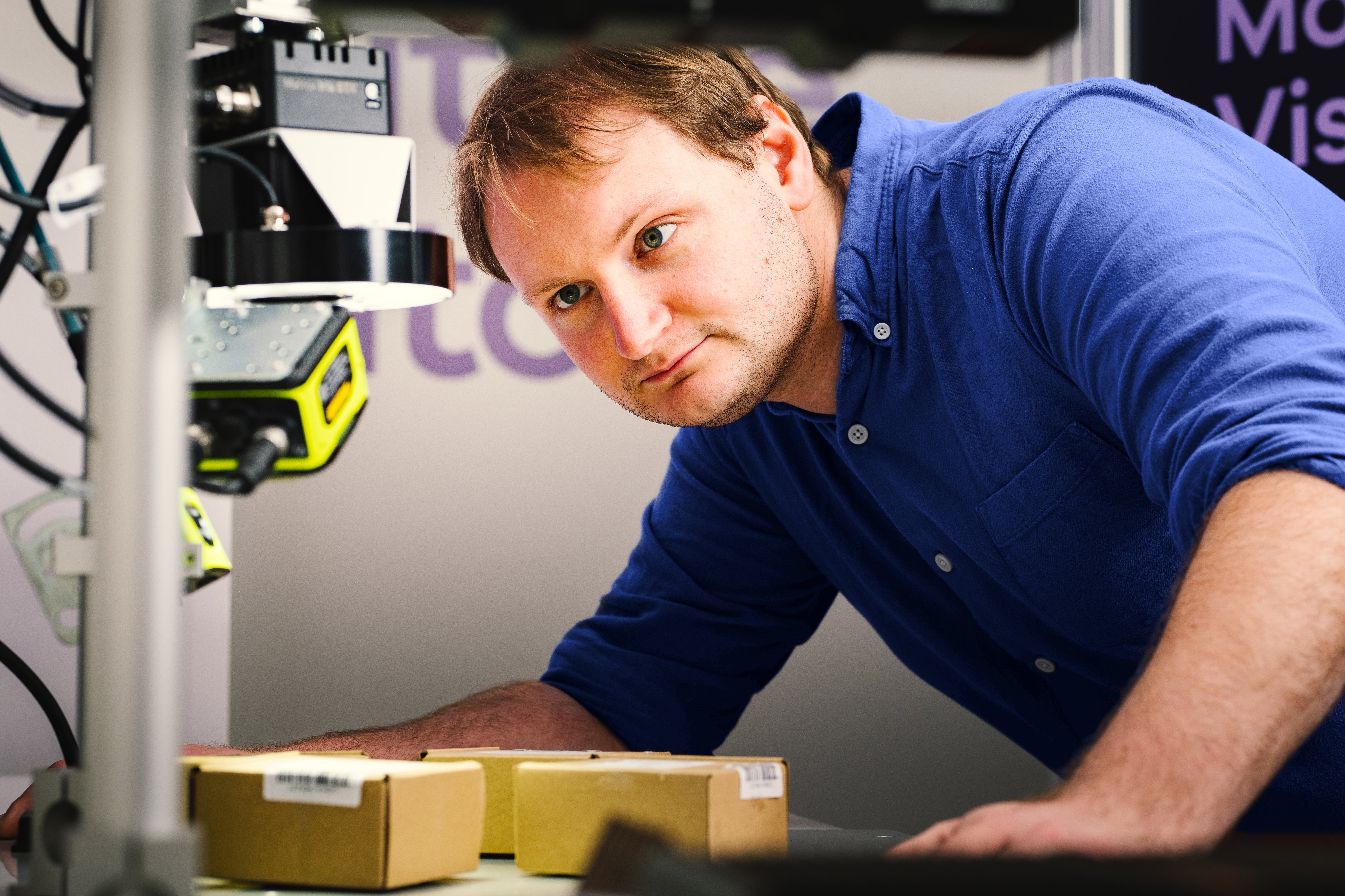
Inspection throughput is ultimately limited not by camera frame rate but by the slowest link in the chain: illumination settling time, image transfer bandwidth, or the processing time of the classification algorithm.
How Does Lighting Geometry Reveal Cracks and Surface Defects?
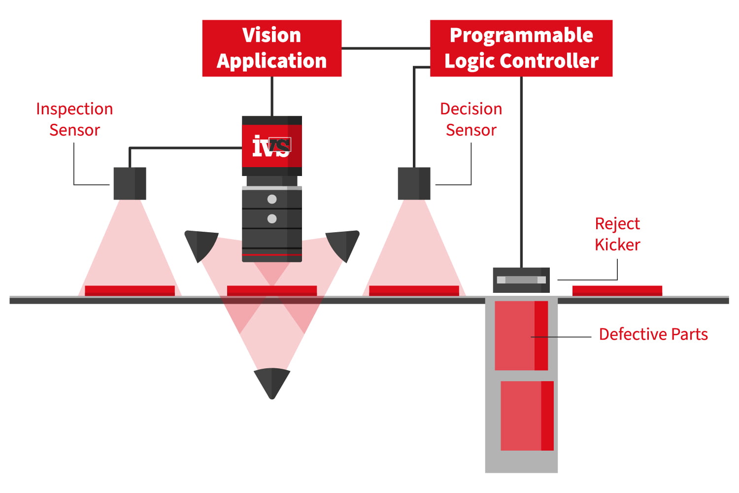
Illumination design determines whether a defect produces enough contrast to be captured at all, regardless of camera resolution. Dark-field lighting, where light sources are angled obliquely to the wafer surface, is standard for revealing microcracks and scratches because these features scatter light differently than the surrounding flat surface, creating a bright line against a dark background. Bright-field, direct illumination is better suited to detecting stains, discoloration, and printing defects on the silver conductive fingers, where the contrast mechanism relies on absorption differences rather than surface scattering.
Structured or patterned lighting adds a further capability: projecting a grid or fringe pattern onto the wafer surface allows the vision system to reconstruct surface topology and detect warping or bowing that neither dark-field nor bright-field imaging would reveal on their own. Custom machine vision systems built for a specific cell line often combine two or three of these lighting modes on a single inspection station, switching between them synchronously with the camera’s frame rate so that a single wafer pass yields multiple complementary images for the classification software to evaluate together. ClearView Imaging
Photoluminescence and electroluminescence imaging occupy a separate category entirely, since they measure the cell’s own light emission under electrical bias or laser excitation rather than reflecting external light. These techniques reveal shunting defects, broken fingers, and inactive cell regions that produce no visible contrast under conventional illumination, making them indispensable for final electrical performance verification even though they require specialized cameras sensitive in the near-infrared band around 1,100 nanometers.
What Role Does Machine Learning Play in Classifying Ambiguous Defects?
Rule-based image processing, using thresholding, edge detection, and blob analysis, handles the majority of clear-cut defects efficiently and predictably, but it struggles with borderline cases where a mark could be a benign process artifact or an early-stage crack. This is where machine learning vision systems add measurable value, since a convolutional neural network trained on a labeled dataset of thousands of prior wafer images can learn subtle texture and shape patterns that are difficult to encode as explicit rules. In practice, manufacturers often run both approaches in parallel: rule-based logic handles high-confidence pass and fail decisions instantly, while ambiguous cases are routed to the trained model for a secondary classification pass.

Training data quality matters more than model architecture in most deployments. A network trained primarily on defects from one production line’s lighting and camera configuration will often underperform when transferred to a second line with slightly different optics, which is why integrators typically retrain or fine-tune models after any significant hardware change. For further technical background on structuring these classification pipelines, some integrators reference machine vision lenses when documenting validated configurations for specific cell technologies.
Sample Calculation: Estimating Inspection Station Throughput
Which System Specifications Matter Most When Comparing Vendors?
| Inspection Tier | Typical Sensor Resolution | Line/Frame Rate | Defect Detection Focus | Typical Integration Complexity |
|---|---|---|---|---|
| Entry-level cell sorting | 2-5 MP area scan | 30-60 fps | Gross cracks, chips, color sorting | Low; standalone smart camera |
| Mid-range wafer inspection | 8-12 MP area scan or 4K line scan | 100-300 fps / 20 kHz line rate | Microcracks, finger defects, edge chips | Moderate; PC-based with lighting controller |
| High-throughput production line | 16-25 MP or 8-16K line scan | 60-100 kHz line rate | Sub-20-micron cracks, saw marks, warp | High; multi-camera synchronized array |
| Electroluminescence final test | 2-5 MP InGaAs/NIR sensor | 1-10 fps (long exposure) | Shunts, broken fingers, inactive regions | High; requires electrical bias fixture |
How Should Integrators Approach a Custom Inspection Deployment?
- Define the defect catalog and minimum detectable feature size based on the specific cell or panel technology being produced.
- Select camera type, resolution, and lens combination that satisfies the pixel-per-defect requirement at the required line speed.
- Design and validate lighting geometry using sample defective units pulled from existing production, not synthetic test targets alone.
- Build and label a training dataset for any machine learning classification component, sourcing images directly from the target line where possible.
- Run parallel validation against manual inspection or a trusted reference method for a defined trial period before full cutover.
Making the Inspection Investment Pay Off
Frequently Asked Questions
How much does an industrial machine vision inspection station typically cost for a solar production line?
Costs vary widely based on resolution, lighting complexity, and whether electroluminescence testing is included, but a mid-range wafer inspection station with cameras, lensing, lighting, and basic software typically represents a significant capital investment comparable to other single-station process equipment on the line. Electroluminescence stations with electrical bias fixtures generally cost more due to the specialized NIR sensors and fixture engineering involved.
Can one vision system handle both wafer inspection and finished panel inspection?
Generally no, since wafer inspection requires high-resolution optics for micron-scale defects at close working distance, while panel inspection covers a much larger area with different defect types like frame damage or junction box misalignment. Most production lines deploy separate, purpose-built stations at each stage rather than trying to adapt one system for both.
How long does it take to train a machine learning model for defect classification on a new line?
Initial model training typically requires several weeks to a few months, depending on how quickly a sufficiently large and well-labeled dataset of defective and good samples can be collected from the actual production line. Fine-tuning after hardware changes is usually faster since the base model architecture can often be reused.
What happens if the vision system produces too many false positives?
Excessive false positives typically indicate that lighting or threshold settings are too sensitive, or that the classification model was trained on a dataset that doesn’t fully represent normal process variation. Adjusting detection thresholds and expanding the training dataset with more borderline “good” samples usually resolves the issue without sacrificing true defect sensitivity.
Is telecentric lens necessary for all wafer inspection applications?
No, telecentric lenses are primarily justified for precision dimensional measurement tasks like edge chamfer or chip depth analysis where perspective distortion would introduce measurement error. For general surface defect scanning across a full wafer, a well-corrected fixed-focal-length lens is usually more practical and cost-effective.
